What Elastic and Plastic Deformation Mean in Material Behavior
When a metal part bends and stays bent, or when a blade begins to deflect under load and never fully recovers, the material has crossed a line that cannot be undone. Engineers and fabricators who understand where that line sits make better decisions about material selection, part design, and cutting parameters. When force is applied to a metal or engineered material, it may respond in two fundamentally different ways. In the elastic stage, the material stretches or compresses but returns to its original shape once the load is removed. When the applied stress surpasses this point, the material enters the plastic stage, where the shape change becomes permanent. Knowing where that boundary sits, and what drives it, is what separates a well-specified part from one that fails in service.
Key Factors That Influence Deformation Behavior
Several variables determine how a material responds when stress is applied. Understanding these factors helps explain why two metals with similar compositions can behave very differently under load:
- Material composition and base alloy chemistry
- Internal grain structure and grain boundary characteristics
- Temperature at the time of loading
- Rate at which force is applied
- Presence of impurities or inclusions
- Heat treatment history and residual stress state
- Stress concentration areas such as notches, holes, or sharp corners
Quick Check
What causes a material to transition from elastic to plastic deformation?
How the Elastic Region Behaves
In the elastic stage, a material’s response is directly proportional to the applied force. This relationship follows Hooke’s Law, where stress equals the elastic modulus multiplied by strain. For steel, the elastic modulus typically sits around 200 GPa, meaning it takes substantial force to produce even small amounts of elastic strain. The response is fully reversible: once the load is removed, atomic bonds return to their equilibrium positions and the part recovers its original dimensions. The elastic region represents the safe operating range for most structural components, where repeated loading cycles do not cause cumulative dimensional change or long-term performance loss. For designers, keeping working stresses well within the elastic region is the standard starting point for any load-bearing component.
What Happens When Materials Enter the Plastic Region
Once a metal or alloy crosses the elastic limit on the stress–strain curve, it enters the plastic region. During this stage, atomic bonds shift and dislocations within the crystal lattice begin to move. Planes of atoms slide past one another in a process called slip, which allows the material to deform without fracturing. Even after the load is removed, some distortion remains. This shift marks a change not only in shape but also in the material’s internal structure. In many metals, repeated plastic deformation actually increases hardness through a process called strain hardening or work hardening, where dislocation movement becomes progressively more difficult as dislocations accumulate and interfere with one another. In other materials, continued plastic deformation simply leads toward fracture with no strengthening effect.
Important Limits on the Stress–Strain Curve
| Property | What It Indicates |
| Elastic Limit | Maximum stress a material can withstand and still return to its original shape |
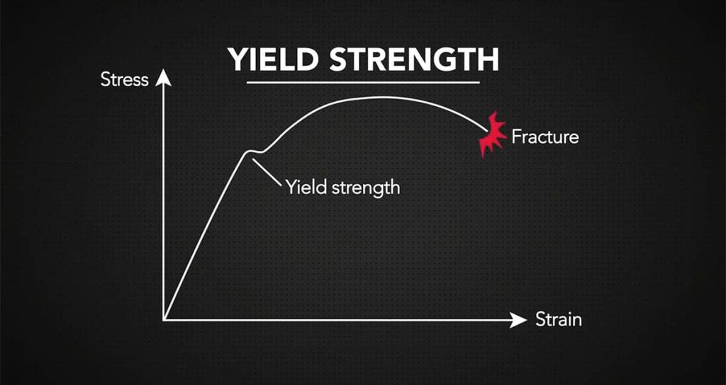
| Yield Strength | Point where permanent deformation begins, often defined using the 0.2% offset method |
| Tensile Strength | Highest stress the material can handle before necking and failure begin |
| Fracture Point | Stage where the material fully separates under load |
Understanding these four values for any given material gives engineers and fabricators a complete picture of how that material will behave across its full loading range. Material datasheets for metals like 304 stainless steel, 6061-T6 aluminum, or 4140 alloy steel all publish these values, and they form the basis for most structural and forming calculations.
Why Yield Strength Matters for Part Design and Material Selection
Yield strength is often the most useful single value when choosing a material that must hold its shape under load. Once a part reaches the plastic stage, its geometry changes permanently, which may affect fit, function, assembly tolerances, or safety margins. Designers typically apply a safety factor, commonly between 1.5 and 3 depending on the application and the consequences of failure, to ensure working stresses stay well below yield. A structural beam sized only to its yield strength offers no margin for unexpected overloads, vibration, or the stress concentrations that exist around fastener holes and welds.
For fabricators working with band saw blades, yield strength also determines how much blade tension can be applied before permanent stretch sets in, and how aggressively a material can be fed into a cut without causing blade deflection, tooth set loss, or blade body fatigue.
Quick Check
Plastic deformation always indicates that a material has failed and is no longer usable.
ALSO WORTH READING
Understand How Ductility Affects Your Material Choices
If you want to go deeper on how materials behave once they enter the plastic region, read “Ductility Explained: How to Measure and Why It’s Important.” It covers how ductility is measured, what it reveals about a material’s capacity to deform before fracture, and why it plays a key role in forming, shaping, and material selection. A practical next step for anyone working through the fundamentals of mechanical behavior.
How to Read a Stress–Strain Curve
A stress–strain curve packs a significant amount of information into a single graph. Reading it correctly allows fabricators and engineers to extract practical data about any metal:
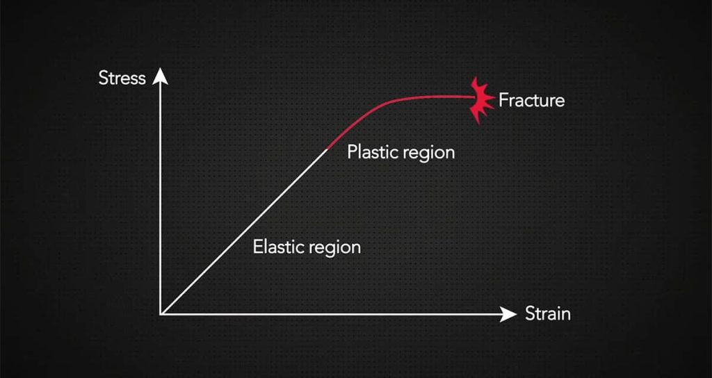
- The initial linear slope represents the elastic region. The steeper the slope, the stiffer the material. For steel, this section is steep; for aluminum, it is noticeably less so.
- The point where the curve becomes nonlinear marks the proportional limit and, shortly after, the yield strength.
- The peak of the curve represents tensile strength, the maximum stress before localized necking begins.
- The endpoint of the curve marks the fracture point, where the material separates completely.
- The total area under the curve represents toughness, measured by how much energy the material can absorb before fracture. A wide, tall curve indicates both strength and ductility.
For ductile materials like low-carbon steel, the curve shows a long plastic region between yield and fracture. For brittle materials like gray cast iron, that plastic region is short or nearly absent, and fracture follows yield with little warning.
Common Signs a Material Has Exceeded Its Elastic Limit
- Permanent bending that does not spring back when the load is removed
- Visible stretching or elongation of the part
- Thinning or necking of the cross-section
- Loss of original dimensional form or assembly fit
- Reduced ability to support rated load
- Nonlinear response on a stress–strain graph
- Surface orange peel texture or waviness in sheet metal forming
Differences Between Ductile and Brittle Behavior
Ductile materials show visible, measurable deformation before failure. This warning allows users, maintenance teams, and safety systems to identify problems before a catastrophic break occurs. Steels, aluminum alloys, and copper alloys typically exhibit ductile behavior. When a ductile steel bar begins to neck visibly before breaking, that is the plastic region doing its job, absorbing energy and providing a warning.
Brittle materials, including gray cast iron, hardened tool steels, ceramics, and many intermetallics, tend to fail suddenly. Fracture follows yield at a very small or near-zero plastic strain, with no visible necking or elongation. For structural applications and components under cyclic loading, this difference is significant. A brittle failure can occur without any prior visible indication, making material selection and stress analysis particularly important in those contexts.
How Tensile Strength Relates to Plastic Deformation
Tensile strength defines how much stress a material can sustain during the plastic stage before failure begins. Ductile materials typically stretch noticeably during this phase, with visible necking at the failure point. Brittle materials, however, transition from yield to fracture quickly, sometimes with no measurable plastic strain at all. For band saw blade selection specifically, tensile strength matters because blade bodies and tooth tips experience cyclic stresses that can push materials through repeated elastic cycles and into the plastic range under aggressive cutting conditions. Selecting blade materials with adequate tensile strength and toughness reduces the risk of unexpected fracture during production cuts.
When Plastic Deformation Is Part of the Process
Plastic deformation is not always a problem. In many manufacturing operations, it is the entire point. Processes that depend on controlled plastic deformation include:
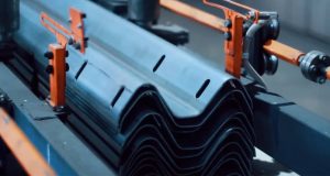
- Bending and forming: sheet metal parts achieve their final geometry through permanent plastic strain applied in a press brake or roll former.
- Drawing: wire, tube, and rod stock are reduced in cross-section by pulling material through a die, with each pass introducing a controlled amount of plastic strain.
- Forging: compressive plastic deformation at elevated temperatures refines grain structure and improves mechanical properties compared to cast alternatives.
- Rolling: plate and structural stock are reduced in thickness through plastic compression between rolls, often with multiple passes.
- Cold working: intentional plastic strain introduced below the recrystallization temperature increases yield strength through dislocation hardening, allowing thinner or lighter sections to carry the same load.
In each of these processes, the goal is controlled deformation that stops well short of fracture. That requires knowing both the yield strength and the extent of the plastic region for the specific material being processed.
Quick Check
What is the typical elastic modulus of steel in GPa? Drag to answer.
Frequently Asked Questions About Elastic and Plastic Deformation
What is the main difference between elastic and plastic deformation?
Elastic deformation is temporary and fully reversible: the material returns to its original shape when the load is removed. Plastic deformation is permanent: the material retains some portion of the shape change even after the load is gone.
What causes a material to transition from elastic to plastic deformation?
The transition occurs when applied stress exceeds the material’s yield strength. At this point, dislocations in the crystal lattice begin to move and atomic planes slip past one another, causing permanent shape change that cannot be recovered by simply removing the load.
Is plastic deformation always a sign of failure?
Not always. In manufacturing processes like forming, drawing, and forging, plastic deformation is intentional and necessary. It only represents failure when it occurs in a component that must maintain dimensional accuracy in service, or when it progresses far enough to cause fracture.
How does yield strength affect cutting performance?
Materials with high yield strength resist plastic deformation under cutting forces, which generally means harder, more abrasion-resistant surfaces. They also tend to generate more heat during cutting and place higher demands on blade geometry and tooth pitch. Matching blade specifications to the yield strength and hardness of the workpiece is one of the more reliable ways to extend blade life and maintain cut quality.
Why do brittle materials fracture with little warning?
Brittle materials have very limited capacity for dislocation movement within their crystal structure. When applied stress reaches the fracture threshold, there is little energy absorbed through plastic deformation beforehand, so the crack propagates rapidly and without visible warning signs like necking or elongation.
Test Your Understanding of the Plastic Region
Want to check your understanding of material behavior under load? Visit SawbladeUniversity.com and take the quick quiz on The Plastic Region. It is a straightforward way to confirm your knowledge, reinforce key concepts, and build confidence in recognizing how materials respond once they pass the elastic limit.
Applying This Knowledge to Material and Blade Selection
Recognizing the difference between elastic and plastic deformation helps predict how materials respond to stress, how long they may last in service, and how they should be selected for industrial or structural applications. Yield strength and tensile strength provide reliable reference points, helping fabricators, designers, and builders choose metals that match their actual requirements rather than over-specifying or under-specifying for the job.
For cutting applications, this knowledge extends directly into blade selection. Matching tooth geometry, blade material, and cutting parameters to the deformation characteristics of the workpiece reduces tool wear, improves cut quality, and extends blade life. A material that deforms plastically under light cutting pressure requires a different approach than one that stays elastic right up to the point of fracture. Understanding the difference is what makes the selection process reliable rather than guesswork.